The Robot

Overview

This robot is designed to compete in the Robocup Junior Soccer A Lightweight competition. In the game, there is an electronic ball that gives off an infrared signal. Teams consisting of two 1.25kg robots play against each other on a 1.2m × 1.8m pitch. There are rules governing the size and shape of the robots. The robots play football autonomously for two 10 minute halves.

A short video of the robot in action can be found on youtube

I entered this competition with my friend Andrew Wightwick. He focused on the chassis design and manufacturing, while I was more involved in the electronics and software aspect of the robot. As such, this document does not describe the entirety of the robot.

Version control - Git

To keep track of the software as it was written, as well as this document, a distributed version control system was used - Git. Essentially, this allows changes to be "committed" to a history, such that you can see what changes have been made, as well as revert to older versions.

Additionally, it provides a maintainable way of working from multiple locations. The Git repository containing this information, as well as being stored locally, can be "pushed" to a remote server. This can then be "pulled" off the server to a different computer, which means that if work is lost, it can be restored from the online copy.

To host my Git repositories, I used github. One repository contains the entire code library for the robot, spanning 6000 lines of code. The other repository contains this write up, in electronic form.

Controller

FEZ Panda II
The controller

The controller can be though of as the "brain" of the robot. It reads from and writes to the sensors, and drives the robot in response.

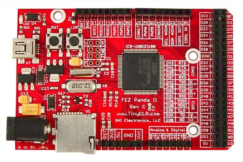
The robot uses a FEZ Panda II, from GHI Electonics. It's an Arduino based design, but boasting more GPIO pins, and programmed in C#, rather than C++. I'd had experience with the Arduino before, but had found the software frustrating. Since the FEZ runs the .NET Micro Framework, C# is available, which is a much nicer language.

Wheels

The wheels are designed such that they are effectively frictionless in one axis. This is achieved by mounting a set of smaller perpendicular wheels around the circumference. These smaller wheels are free to turn even when the main wheel is held still, allowing a free component of motion along the axis of the wheel. At the same time, the wheel can be powered as normal wheel.

The small wheels in my design are washers. These are sufficient, as the sharp edge of the washer provides plenty of friction in the direction of drive, and the perpendicular friction is fairly low. Additionally, washers are cheap! The axles for the washers needs to be a ring. The easiest way to get a ring is from a keychain. The ones the wheels use is a 5.1mm split ring. The next thing needed is a way of holding the split ring onto the motor shaft. This was done with a circular laser-cut aluminum hub, held onto the split ring with cable ties.

The most time consuming part of this aspect of the artefact was designing the aluminum hub. This is partly because of the accuracy required. A technical drawing program was used to design this. The design went through multiple sizes, as the measurements of the washers and split ring were gradually improved. The final design was set off to microkerf, where it was laser cut in 4mm aluminum.

Motors and Drivers

The motors chosen can take up to 3.3A of current. In order to drive these safely, the driver chips have to be able to take at least this much current. Initially, the plan was to buy pre-built motor drivers, but they were generally too expensive, and either insufficiently powerful, or much more powerful then they needed to be. In the end, I decided to build the drivers myself.

The chip used was an L298 dual H-bridge, which allows two DC motors to be powered in both direction, drawing up to 2A of current. By paralleling the outputs, a current of 4A can be drawn. This is more than than the motors will draw, but it means there's no chance of the chip blowing up. The other thing the driver requires are clamp diodes to clamp the motor outputs to the supply voltage, preventing reverse EMF, which can damage the driver chip.

The original plan was to make a PCB for the entire robot, and assemble the drivers on the PCB. However, PCB fabrication turned out to be expensive, and a lot of work. Instead, the motor drivers were assembled and soldered onto a piece of stripboard, which had the benefit of being prototypable.

More details on how the motor was chosen can be seen in the notes.

Drive system

Throughout this section, vector notation will be used. Vectors are simply a coordinate pair. They can be thought of a value holding size and direction. Variables in bold face are vectors. For convenience, \( \mathbf{v} \equiv \left[\begin{array}{ c } v_1 \\ v_2 \end{array}\right] \).

For any given trajectory of the robot, each point on the robot has it's own unique trajectory. Conversely, by controlling the trajectory of three or more points on the robot, any robot trajectory can be achieved. In our case, the controlled points of the robot are those at the center of the three wheels. By controlling the trajectory of each wheel, the overall trajectory of the robot can be controlled.

Each wheel has two independent vectors of motion. There is the drive vector, \(\mathbf{d}\), which acts tangentially to the large wheel and is proportional to the motor voltage, and the slip vector \(\mathbf{s}\), which acts tangentially to the small wheels, and is independent of the motor voltage. Since these vectors are independent (i.e. not parallel), then any vector can be expressed in terms of \(\mathbf{d}\) and \(\mathbf{s}\):

$$\mathbf{v} \equiv k_d\mathbf{d} + k_s\mathbf{s}$$

Taking \(\mathbf{v}\) to be the desired velocity of the wheel, the formula can be used to find the speed to drive the motor at. This is simply \(k_d\). The trick, of course, is finding the value of \(k_d\). To do this, matrices are required.

The equation above can be rewritten as:

$$\mathbf{v} = \left[\begin{array}{ c c } d_1 & s_1 \\ d_2 & s_2 \end{array}\right] \times \left[\begin{array}{ c } k_d \\ k_s \end{array} \right] $$

Rearranging to find \(k_d\) and \(k_s\):

$$ \left[\begin{array}{ c } k_d \\ k_s \end{array} \right] = \left[\begin{array}{ c c } d_1 & s_1 \\ d_2 & s_2 \end{array}\right]^{-1} \times \mathbf{v} $$

This is the general formula to find the rotational speed \(k_d\) of a wheel with given drive and slip vectors.

There is one more important point to note here. Since there are three wheels, it is sufficient to only control the drive speed, \(k_d\), of each wheel. The slip speed, \(k_s\), will automatically take the correct value. This is true because setting the speed of the motors fully defines the motion of the robot: it is deterministic. This is hard to prove, but easier to demonstrate.

The following C# class can be written to represent a wheel, which allows its target vector to be set. When it is set, it applies the above formula, and sets the speed of the motor.

public class Wheel
{
    public Matrix TransformMatrix;
    public IMotor Motor;

    public Vector TargetVector
    {
        set
        {
            motor.Speed = (TransformMatrix.Inverse * value).X;
        }
    }
}

Straight motion

If the robot follows a straight trajectory, then every point on the robot follows a parallel trajectory. In code:

public SetDriveVector(Vector driveVector)
{
    foreach(Wheel wheel in Wheels)
        wheel.TargetVector = driveVector;
}

Rotation

The formula for the velocity \(v\) of a point of distance \(r\) from the center of rotation, rotating at an angular velocity of \(\omega\) is given by the equation:

$$v = r\omega$$

However, this equation is of limited use. Thinking back to the straight-line driving, it is much more convenient if the variables can be expressed as vectors. It can be seen that the velocity of a point displaced \(\mathbf{r}\) from the center of rotation is a tangent to the circular motion, ie \(\mathbf{v}\) is perpendicular to \(\mathbf{r}\).

From this information, the following equation can be derived:

$$\mathbf{v} = \mathbf{r}^\perp \times \omega$$

Writing this in code:

public SetRotationSpeed(double omega)
{
    foreach(Wheel wheel in Wheels)
        wheel.TargetVector = (wheel.Position - Center).Perpendicular() * omega;
}

Combined Motion

Often, it is useful to turn while driving. This is used extensively to maintain a heading of the robot. It can be non-trivially proven that the velocity of a point on a rotating and moving object is simply the sum of the rotation component plus the motion component. This allows a function to be written to set the rotation speed and drive direction of the robot.

public SetParameters(Vector direction, double rotation)
{
    foreach(Wheel wheel in Wheels)
        wheel.TargetVector = direction + (wheel.Position - Center).Perpendicular() * rotation;
}

Maintaining a Heading

In order to shoot towards the right goal, it is necessary to maintain the heading of the robot. This is done by measuring the heading of the robot, and then using a PID controller to adjust the heading of the robot.

A PID controller is a system used to set an output to a correct value, using negative feedback. It consists of three parts: a Proportional term, an Integral term, and a Differential term. These can be thought of as the error, the total error so far, and the speed at which the error is changing. By summing and scaling these terms, a suitable output for the system can be found to meet the target.

Sensor input

The robot has 4 types of sensor. There is a set of 16 infrared detectors (the TSOP 1138), arranged around the circumference, that can detect the ball. There is a set of four Ultrasonic sensors to detect the walls. There is a compass (the HMC6532) to detect the heading of the robot. Finally, there's a laser diode pointed at a photodiode acting as a light gate, to detect the presence of the ball in the ball holder.

Reading the US and IR sensors

Ultrasonic sensor
The ultrasonic sensor

The ball gives off a 1.2kHz stepped infrared waveform on a 40kHz carrier frequency, which is picked up by the IR detectors on the robot. The signal returned is a PWM signal, with a low pulse every 833µs. The width of this pulse gives the strength of the signal.

To use the US (ultrasonic) sensors, the controller must send a short high pulse. The sensor will then send an Ultrasonic pings, and respond with a pulse, whose width is the time taken to receive a bounce. By using the speed of sound, the distance can be obtained.

Initially, both these sensors were read in a tight loop C# side. However, this had big performance impacts, and therefore accuracy problems - the code had to loop through 20 sensors, and catch microsecond-wide pulses. This simply isn't possible with the managed C# code. The solution to this was to use a feature of the FEZ called "RLP", which stands for "Runtime Loadable Procedure". Basically, this allows me to drop down into native C code, which runs far faster than the managed C# code. With this, I wrote a procedure to read all the sensor information simultaneously, then return it to the managed c# code.

Combining IR sensor readings

To be useful, the readings of all the IR sensors need to be combined to get a single measure of direction. To do this, each sensor was assigned a vector in the software, that points in the direction the sensors faces. By taking the strength of each sensor, multiplying it by the direction vector, and summing the vectors to get a resultant. In code:

public Vector Get() {
    Vector sourceDirection = 0;
    foreach (OrientedSensor sensor in Sensors) {
        sourceDirection += sensor.Intensity * sensor.Direction;
    }
    return sourceDirection;
}

The result is also scaled, but this is not significant.

Using the compass

HMC6352 I²C Compass
The compass

The compass is an I²C device. An I²C driver is build into the FEZ, so using the sensor is trivial. I²C is a data protocol running on two wires. Put simply, the master device (the FEZ) issues a read request, and the slave device (the compass) responds with bytes of data.

By reading a pair of I²C registers, and writing some commands, the compass heading can be obtained, in degrees. This is then converted to radians, for convenience.

The purpose of the compass is to keep the robot shooting in the right direction. Upon start up, the robot records the compass heading, which is the direction of the opponent goal. This is then compared with the compass heading to find the field-relative robot orientation.

Using the light gate

The laser is connected directly to the power supply coming from the FEZ. Originally, it was connected to the 5V supply, but this was deemed "Extremely blinding", so was taken down to 3.3V.

Laser and photodiode
The light gate

The photodiode generates electricity when the laser points at it. This generated voltage can be measured by the FEZ, on an analog input. When the beam is unbroken, it hits the photodiode, and a voltage is generated. If the beam is broken (by the ball), the photodiode generates a lower voltage. By comparing the voltage across the photodiode to a known threshold value, it can be determined whether the light gate is obstructed.